CIE A Level Physics復(fù)習(xí)筆記20.1.6 Hall Voltage

Hall Voltage
- The Hall voltage is a product of the Hall effect
- Hall voltage is defined as:
The potential difference produced across an electrical conductor when an external magnetic field is applied perpendicular to the current through the conductor
- When an external?magnetic field?is applied perpendicular to the direction of current through a conductor, the electrons experience a?magnetic force
- This makes them drift to one side of the conductor, where they all gather and becomes more negatively charged
- This leaves the opposite side deficient of electrons, or positively charged
- There is now a potential difference across the conductor
- This is called the Hall Voltage,?VH

The positive and negative charges drift to opposite ends of the conductor producing a hall voltage when a magnetic field is applied
- An equation for the Hall voltage?VH?is derived from the electric and magnetic forces on the charges
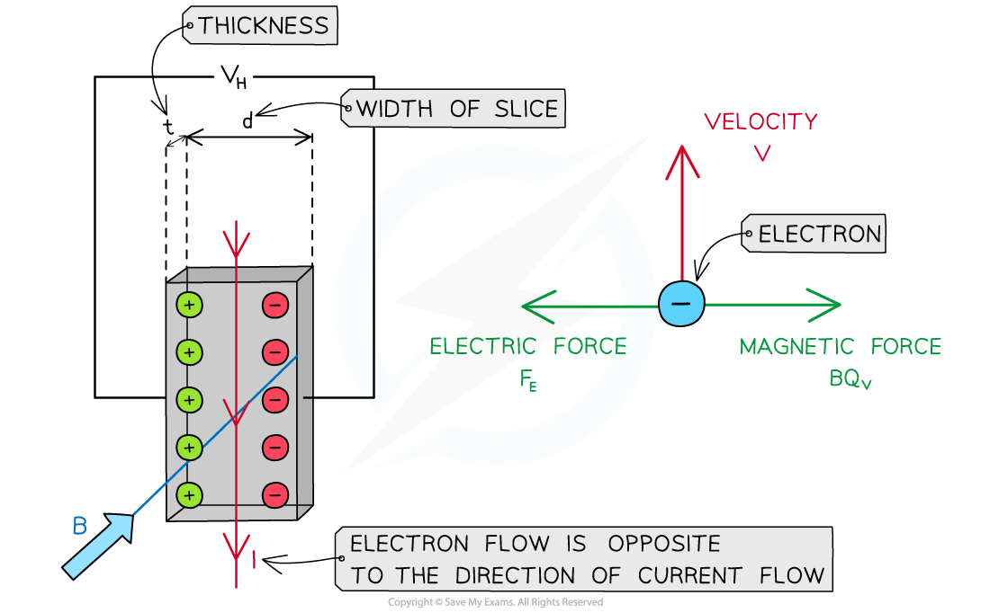
The electric and magnetic forces on the electrons are equal and opposite
- The voltage arises from the electrons accumulating on one side of the conductor slice
- As a result, an electric field is set up between the two opposite sides
- The two sides can be treated like oppositely charged parallel plates, where the electric field strength?E?is equal to:

- Where:
- VH?= Hall voltage (V)
- d = width of the conductor slice (m)
- A single electron has a drift velocity of?v?within the conductor. The magnetic field is into the plane of the page, therefore the electron has a magnetic force FB?to the right:
FB?= Bqv
- This is equal to the electric force FE?to the left:
FE?= qE
qE = Bqv
- Substituting E and cancelling the charge q

- Recall that current?I?is related to the drift velocity?v?by the equation:
I = nAvq
- Where:
- A = cross-sectional area of the conductor (m2)
- n = number density of electrons (m-3)
- Rearranging this for?v?and substituting it into the equation gives:

- The cross-sectional area?A?of the slice is the product of the width?d?and thickness?t:
A = dt
- Substituting?A?and rearranging for the Hall voltage?VH?leads to the equation:


- Where:
- B = magnetic flux density (T)
- q = charge of the electron (C)
- I = current (A)
- n = number density of electrons (m-3)
- t = thickness of the conductor (m)
- This equation shows that the smaller the electron density n of a material, the larger the magnitude of the Hall voltage
- This is why a semiconducting material is often used for a Hall probe
- Note:?if the electrons were placed by positive charge carriers, the negative and positive charges would still deflect in opposite directions
- This means there would be no change in the polarity (direction) of the Hall voltage
Exam Tip
Remember to use Fleming’s left-hand rule to obtain the direction the electrons move due to the magnetic force created by the magnetic field.
轉(zhuǎn)載自savemyexams
以上就是關(guān)于【CIE A Level Physics復(fù)習(xí)筆記20.1.6 Hall Voltage】的解答,如需了解學(xué)校/賽事/課程動(dòng)態(tài),可至翰林教育官網(wǎng)獲取更多信息。
往期文章閱讀推薦:
2026 ALEVEL 夏考A率出爐!愛德思vs牛津AQA,哪些科目真的“好出分”?
2026 AMC10/12美國數(shù)學(xué)競賽新賽季!【翰林教育 × 清華大學(xué)出版社】獨(dú)家教材全面發(fā)售!


翰林AMC8視頻課重磅上線!

國際競賽真題資源免費(fèi)領(lǐng)取